


Key Takeaways
- Crankshaft bearings and connecting rod bearings support and protect the crankshaft in diesel and heavy equipment engines, allowing smooth rotation under extreme loads.
-
Bearing size is checked by reading markings on old bearing shells and by measuring crankshaft journals and housing bores with a micrometer and bore gauge. Measuring bearing inside diameter with a dial bore gauge and journal size with a precision micrometer is essential for accurate clearance checks.
- Choosing the right size means matching OEM specs, maintaining proper oil clearances, and accounting for engine condition.
- Replacing bearings requires clean work surfaces, correct torque sequences, and plastigage or measurement checks before final assembly. Journals bearings, and tools must be completely free of oil film or debris, and measurements should be taken at room temperature to avoid errors.
- When clearances fall outside specifications, the solution often involves crankshaft regrinding at a machine shop and selecting matching undersize bearings. Plastigage is a plastic wire that is crushed between the bearing and journal to show clearance.
If you’ve ever disassembled an engine and wondered how to verify if your crankshaft and rod bearings are the right size, you’re not alone. It may seem daunting, but becomes simple once you grasp the process.
This guide covers everything you need to know about checking, choosing, and replacing crankshaft main bearings and connecting rod bearings. Whether you’re working on a Komatsu, Cummins, or Caterpillar engine, the fundamentals are the same.
What Are Crankshaft Bearings and Con Rod Bearings?
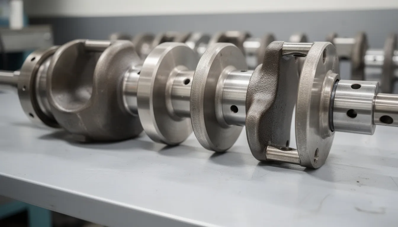
Crankshaft main bearings are precision components that sit in the engine block and support the rotating crankshaft. Think of them like the foundation of a building—they keep the crankshaft centered and control the critical oil clearance that allows a thin film of oil to separate metal surfaces during operation.
Connecting rod bearings, often called rod bearings or con rod bearings, serve a similar purpose but in a different location. They fit between the connecting rods and the crankshaft's crankpin journals. Every time a piston fires and pushes down, these bearings absorb tremendous forces while allowing the crankshaft to rotate smoothly.
Both types are “plain” bearings, meaning they rely entirely on oil pressure rather than rolling elements. They typically come as bearing shells made in two halves—an upper and lower shell that wrap around the journal. Modern shells feature multi-layer construction with a steel backing, a copper-lead or aluminum-tin alloy layer, and sometimes a soft overlay for embedability.
For heavy equipment operators running Komatsu, Caterpillar, Cummins, Volvo, or Doosan engines, these bearings handle punishing workloads day after day. When bearings wear beyond acceptable limits or when someone installs the wrong size, problems show up fast: low oil pressure readings, a distinct knocking sound, metal particles in the oil, and in worst cases, complete crankshaft failure.
Why Bearing Size Matters
When we talk about bearing “size,” we're really discussing two related things: the physical thickness of the bearing shell and the resulting oil clearance between the crankshaft journal and the bearing surface. Get this wrong, and you're looking at expensive problems.
Common bearing sizes include:
- Standard (STD) - Fits factory-dimension crankshaft journals
- 0.25 mm undersize (0.010") - For cranks ground down one step
- 0.50 mm undersize (0.020") - For cranks ground two steps
- 0.75 mm undersize (0.030") - For cranks ground thress steps
Fab Heavy Parts follows these OEM size increments to ensure compatibility with properly reground crankshafts.
Here's the critical point: if a machine shop grinds your crankshaft 0.25 mm undersize to remove wear or damage, you must install matching 0.25 mm undersize bearings. The thicker shells compensate for the smaller journal diameter, maintaining the same oil clearance as the original setup.
Too much clearance causes oil pressure to drop and allows the crankshaft to knock against the bearing. Too little clearance generates excessive heat and can lead to seizure. For work machines that run eight, ten, or twelve hours daily, correct clearance is essential for long service life. It's not something you want to approximate—you need to verify it before buttoning up that engine.
How to Check Crankshaft Bearing Size
This section gives you a practical approach to checking crankshaft main bearing size using common tools available in most shops. The goal is to determine exactly what size bearings your engine needs before you place an order.
Required tools:
- Outside micrometer (appropriate range for your engine, such as 50–75 mm or 2”–3”)
- Dial bore gauge
- Precision micrometer (essential for measuring journal sizes accurately)
- Dial bore gauge (required to measure the inside diameter of main or rod bearings)
- Torque wrench (calibrated)
- Plastigage strips
- Clean lint-free rags
- Engine service manual with specifications
Using sufficient and proper tools for this task, such as a precision micrometer and a dial bore gauge, is critical to achieve accurate measurements and avoid error.
You can determine bearing size three ways: by reading markings on existing bearings, by measuring crankshaft journal diameters, and by measuring housing bores and calculating clearances. For best accuracy, use all three methods and double check your findings before ordering parts.
All measurements must be taken at room temperature. Journals and caps need to be perfectly clean—any oil film or debris throws off readings. Before measuring, inspect the crankshaft for visible scoring, heat discoloration, or taper. If journals look damaged, they’ll likely need grinding regardless of what the numbers say.
It is important to zero the micrometer before use and to use a consistent measurement technique to avoid errors and ensure accurate results.
Step 1 - Read the Markings on the Old Crankshaft Bearings
Many OEM and aftermarket bearing shells, are stamped on the back with size codes. This is often the fastest way to identify what's currently installed.
To check the markings:
- Remove a main bearing cap using the proper sequence
- Carefully lift out the old bearing shell without scratching the bore
- Wipe the back of the shell clean and look for stamped codes
Common markings you'll find:
- “STD” = Standard size for unground crankshaft
- "0.25" or "0.25 U/S" =0.25 mm undersize
- "0.10" = 0.010" undersize (imperial equivalent of 0.25mm)
- "0.50" or "020" = 0.50mm / 0.020" undersize
If codes are missing, worn off, or unreadable, you'll need to rely on direct measurements and engine documentation. Don't guess.
Keep in mind that if the crankshaft has been reground previously, all main journals are usually the same undersize. However, some heavy-duty engines allow different undersizes on different journals if wear patterns varied. Check each journal individually—don't assume they're all identical.
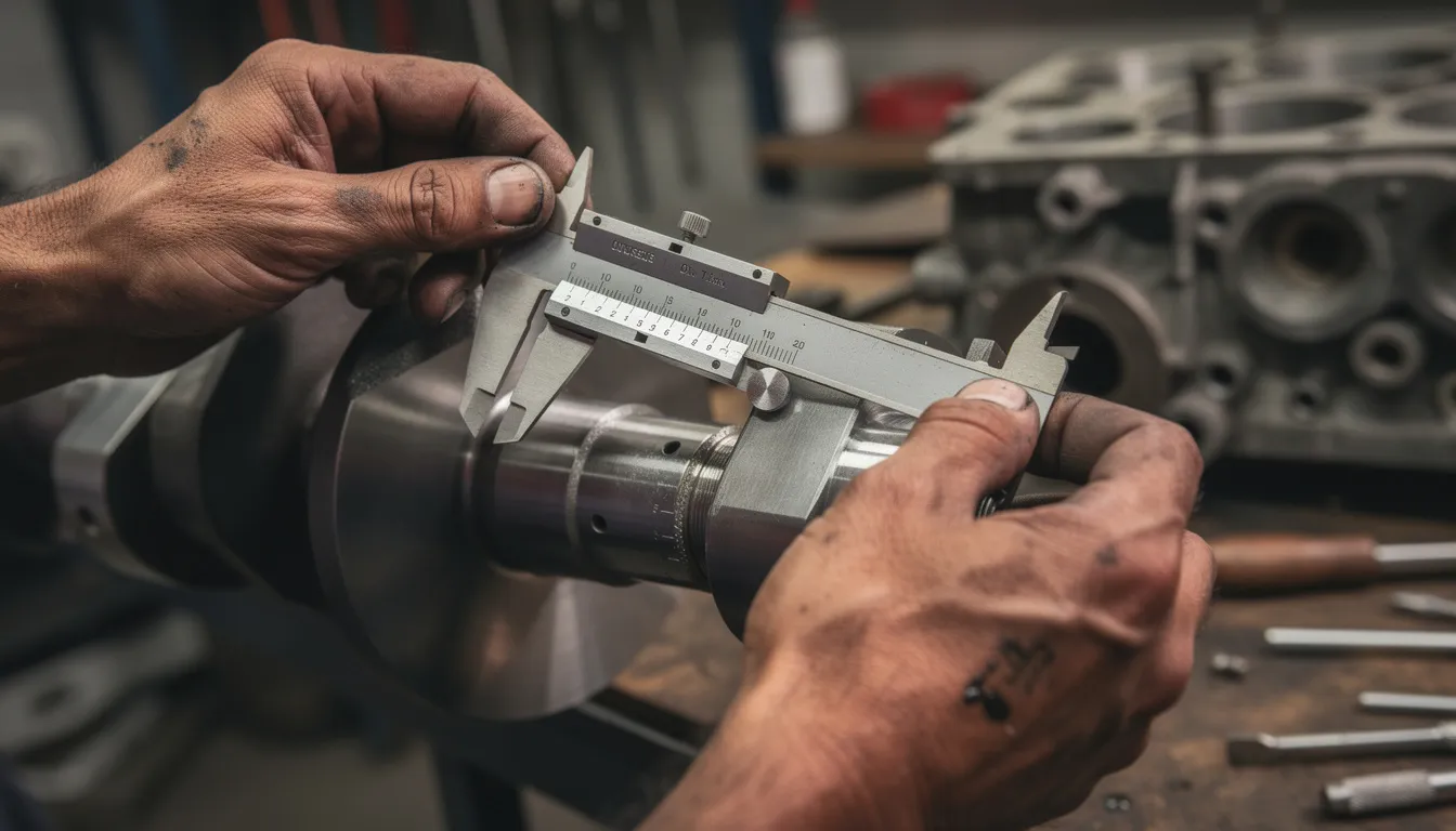
Step 2 - Measure the Crankshaft Main Journals
When measuring rod bearing size, you need to measure the crank journals (main and rod journals) on the crankshaft (shaft) itself. Using an outside micrometer, measure each main journal’s diameter at multiple positions. Take readings at 0°, 90°, 180°, and 270° around the journal, and at two or three points across its width. This ensures you accurately assess the condition of the crank journals and rod journals.
Example measurements:
For an engine with a nominal main journal diameter of 70.000 mm:
- Standard specification range: 70.000–70.013 mm
- If you measure 69.75 mm: This indicates a 0.25 mm undersize grind
- If you measure 69.50 mm: This indicates a 0.50 mm undersize grind
Always use the same micrometer for all measurements to avoid error. It is best to measure crankshaft journals in multiple locations and at 90-degrees to the parting line to determine minimum clearance.
Compare your readings to the OEM specifications in your service manual. The manual should list standard dimensions and all available undersize grinding steps for that specific engine model.
Pay attention to taper and out-of-round conditions. If measurements vary more than 0.005–0.010 mm around a single journal, the crankshaft needs machining before new bearings will survive. Installing fresh bearings on an out-of-round journal is like trying to deposit money into a checking account that’s already closed—the transaction simply won’t work properly.
When your measured journal size matches a known undersize step, note that size for ordering. For a 0.25 mm undersize reading, you’d order 0.25 mm undersize crankshaft main bearings from Fab Heavy Parts.
To measure bearing clearance, compare the measured journal diameter to the bearing inside diameter.
Step 3 - Measure the Main Bearing Housing Bore (Optional but Recommended)
For the most accurate picture, measure the main bearing housing bores—also known as the main tunnel, the passage in the engine block that houses the crankshaft and main bearings—with a dial bore gauge. This step confirms that the block saddles and caps are within specification.
Here’s how to proceed:
- Install main bearing caps without any bearing shells
- Torque cap bolts to specification in the correct sequence
- Set up your dial bore gauge using a micrometer adjusted to the nominal housing size from your manual
- Insert the gauge and read the actual bore size of the main tunnel
- Check for out-of-round by rotating the gauge 90°
When measuring bearing ID, it is important to measure at 90-degrees to the parting line to determine minimum clearance.
Oversized or out-of-round housing bores cause problems that new bearings can’t fix. The bearing shells rely on a properly sized bore to maintain their shape and crush. If housings are damaged, line-boring or block replacement may be necessary before proceeding.
By combining journal diameter, housing bore, and bearing shell thickness data, you can calculate total oil clearance. However, for most rebuilders, using plastigage provides a more practical verification method.
Step 4 - Check Oil Clearance with Plastigage
Plastigage is a plastic wire that is crushed between the bearing and journal during assembly to show clearance. The width of the crushed strip tells you the exact clearance—simple and effective.
Plastigage procedure:
- Clean the journal and bearing surface thoroughly
- Cut a piece of plastigage slightly shorter than the bearing width
- Lay the strip across the top of the journal (parallel to the crankshaft axis)
- Install the bearing cap with new bearing shell
- Torque to specification—do NOT rotate the crankshaft
- Remove the cap and compare the flattened plastigage to the scale on the package
This process helps you measure the bearing inside diameter and main bearing clearance.
Typical main bearing clearance targets:
- 0.038–0.076 mm (0.0015–0.0030”)
- Always verify against your specific engine manual
Bearing clearance is calculated as the difference between the bearing bore inside diameter and the crankshaft journal outside diameter (Bearing Clearance = Bearing Bore I.D. − Crankshaft Journal O.D.). Clearances should be measured at 90-degrees to the parting line to determine the minimum clearance.
If clearance falls outside the service manual range, you have options to consider: a different bearing size might restore proper clearance, or the crankshaft may need regrinding, or the housing may require repair. The plastigage reading tells you what’s happening—it’s up to you to determine the appropriate fix.
How to Check Connecting Rod (Con Rod ) Bearing Size
Checking con rod bearings follows a similar process to main bearings, but you’re working on the rod big ends rather than the block saddles. Because connecting rods endure tremendous reciprocating loads, precise rod bearing clearance is equally critical. Rod bearing clearance is determined by measuring the rod journals on the crankshaft and the rod bearing housing diameter, then calculating the difference to ensure optimal oil flow and engine longevity.
Each rod bearing must be checked individually. In engines that have suffered oil starvation or a spun bearing, damage often concentrates on one or two cylinders while others appear fine. Never assume all rods are the same without measuring.
Safety first: rods and caps are matched pairs from the factory. Mixing them destroys the bore geometry. Keep each cap with its rod, maintain correct orientation (most have markings indicating front/cylinder number), and never swap components between cylinders.
Measuring rod bearing size and clearance involves calculating the difference between the rod bearing housing diameter and the crankshaft journal diameter.
Always reference the exact clearance and torque specifications in your workshop manual. The numbers below are examples—your engine may differ.
Step 1 - Read Markings on Old Con Rod Bearings and Rod Caps
Just like main bearings, con rod bearing shells typically carry size stamps on their backs. These markings help you identify the correct sized bearings needed for engine assembly.
To check:
- Remove one rod cap at a time
- Keep the cap paired with its rod—set them aside together
- Clean the back of the bearing shell and read the code
Example: A rod bearing stamped “0.50” indicates the crankpin journal was ground 0.50 mm undersize. Replacement bearings must also be 0.50 mm undersize. Always use the correct sized bearings—standard or undersized—depending on whether the crankshaft was machined down by a machinist.
Look for color marks or position codes on rods and caps. Manufacturers use these to identify cylinder position and cap orientation. Match marks might appear as numbers (1, 2, 3…) or letters. Some engines use different colored paint dots.
If markings appear inconsistent between cylinders, or if they’re missing entirely, do not assume all rods use the same bearing size. Proceed to direct measurement. Standard vs. undersized bearings must be selected based on whether the crankshaft was machined down.
Step 2 - Measure the Crankpin Journals
Use an outside micrometer sized for your crankpin journals (commonly 45–60 mm or 1.75”–2.25” for many diesel engines) to measure each crank journal (rod journal) on the crankshaft (shaft) at multiple positions.
Example measurements:
For an engine with standard crankpin diameter of 60.000 mm:
- If the same micrometer reads 59.75 mm: Crankpin is 0.25 mm undersize
- If the same micrometer reads 59.50 mm: Crankpin is 0.50 mm undersize
It is best to measure crankshaft journals in multiple locations and at 90-degrees to the parting line to determine minimum clearance. Measuring bearing clearance involves comparing the measured journal diameter to the bearing inside diameter.
Compare each journal’s measurement to your service manual chart. The chart lists standard dimensions and all approved undersize grinding increments.
In some cases, one rod journal may be more worn or differently ground than others. This happens when previous repairs addressed only the damaged journals. You might end up needing mixed bearing sizes—perhaps four rods at STD and two at 0.25 U/S. Fab Heavy Parts can help supply exactly what you need for these situations.
Reject the crankshaft if your find:
- Deep scoring or groove marks
- Blue or purple heat discoloration
- Taper or out-of-round exceeding manual limits
New bearings alone won’t solve these problems. The crankshaft needs professional attention at a machine shop before it’s safe to reuse.
Step 3 - Check Rod Big-End Housing with a Bore Gauge
Measuring the rod big-end bore confirms that the rod hasn’t stretched or distorted—common issues after severe bearing failure. To accurately measure the bearing inside diameter, a dial bore gauge is required.
Procedure:
- Install the rod cap without bearing shells
- Torque the rod bolts to specification
- Set your dial bore gauge from a micrometer at nominal bore size
- Use the dial bore gauge to measure the bearing inside diameter and check for out-of-round by rotating 90°
Rods that are stretched or twisted won’t hold bearings correctly. The crush fit won’t be right, and failure is just a matter of hours. Professional engine shops resize or replace damaged rods—this is standard practice for heavy-duty rebuilds where bearing life and machine uptime matter.
Step 4 - Verify Con Rod Bearing Clearance with Plastigage
The plastigage process for rod bearings mirrors the main bearing procedure. Plastigage is a plastic wire that is crushed between the bearing and journal to show rod bearing clearance.
- Clean the crankpin journal and bearing surfaces completely
- Place plastigage across the crankpin journal
- Install the rod with new bearings, ensuring correct cap orientation
- Torque rod bolts to manufacturer specification
- Remove the cap without rotating the crankshaft
- Compare crushed plastigage width to the scale
Typical con rod bearing clearance ranges:
- 0.030–0.070 mm (0.0012–0.0028”)
- Verify with your engine’s official specifications
Bearing clearance is calculated as: Bearing Clearance = Bearing Bore I.D. − Crankshaft Journal O.D. To determine minimum clearance, measure bearing clearances at 90-degrees to the parting line.
Do not rotate the crankshaft while plastigage is in place—you’ll smear the reading and get inaccurate results. After checking, clean all plastigage residue completely before final assembly.
If clearance is out of spec, the answer isn’t “tighten the bolts harder.” You’ll need to determine whether a different bearing thickness, crankshaft regrinding, or rod resizing is required. Track your findings carefully—like maintaining a bank account statement, good record keeping makes the next steps clearer.
How to Choose the Right Crankshaft and Con Rod Bearings
Once you’ve determined the required size through measurement, the next step is selecting bearings that match your engine, workload, and rebuild goals. Performance bearing manufacturers like Speed-Pro offer a wide range of sized bearings, including extra clearance and undersize parts, to help you achieve more clearance or fine-tune clearances for optimal engine performance. Fab Heavy Parts offers OEM-quality options designed for heavy equipment applications.
Key decision factors:
- Engine model and serial number
- Standard vs. undersize requirement
-
Bearing material and design
- Operating conditions and duty cycle
- Supplier technical support
Adjustments to bearing clearances can be made using extra clearance or undersize parts, and performance bearing manufacturers provide these options to ensure you can select the right sized bearings for your specific needs.
Match Engine Model, Serial Number, and OEM Spec
Start by identifying your exact engine. Examples include Komatsu SAA6D114E-3, Cummins 6BT5.9, Caterpillar C7, or Volvo D12. The serial number provides additional detail about the build configuration.
Where to find engine identification:
- Metal plate on the engine block (often near the injection pump)
- Valve cover decal or stamping
- Data plate on the front timing cover
- Equipment manufacturer's documentation
Fab Heavy Parts cross-references this information against OEM catalogs to provide bearings with correct width, oil hole positions, thrust bearing configuration, and locating tang placement.
Using bearings with wrong width or oil groove design can block oil passages or cause edge loading. It's the mechanical equivalent of writing a check to the wrong payee line—the money goes somewhere, but not where it should.
Standard vs. Undersize Bearings
The rule is simple: match bearing size to journal size.
- Standard (STD): For unground crankshafts at factory dimensions
- Undersize: For reground crankshafts
Example: If your main journals measure 0.25 mm below standard diameter, you need 0.25 mm undersize (0.010”) main bearings.
Bearing manufacturers, including Fab Heavy Parts, clearly stamp the size on both the box and the back of each shell. This prevents mixing during installation.
Critical point: Both halves of a bearing set (upper and lower shells) for a single journal must be the same size. Mixing sizes on one journal creates an immediate failure condition. Fill your order correctly from the start.
Selecting Bearing Material and Duty Rating
Bearings come in different material constructions, each suited to specific applications:
|
Type |
Construction |
Best For |
|
Bi-metal |
Aluminum-tin alloy on steel backing |
Standard duty, clean oil systems |
|
Tri-metal |
Steel backing + copper-lead layer + soft overlay |
Heavy duty, contamination resistance |
Construction, mining, and quarry machines benefit from tri-metal bearings. The copper-lead intermediate layer handles higher fatigue loads, while the soft overlay embeds small contaminants rather than scoring.
Fab Heavy Parts offers bearings designed to meet or exceed OEM fatigue and wear specifications. Choosing properly engineered parts costs less in the long run than bargain bearings that fail prematurely. You can read customer reviews to see how others rate the product quality and reliability. Downtime on a jobsite typically exceeds the price difference between quality and economy parts.
Confirming Clearance Targets Before Final Choice
Following the plastigage verification process, you should know your exact clearance. Setting bearing clearances for both main bearing clearance and rod bearing clearance is critical, as these clearances directly impact engine performance and longevity. Most builders target the middle of the manufacturer’s specified range for general use.
Consider these scenarios:
- If measurements show clearance near the loose end of spec, a crankshaft regrind to the next undersize (with matching undersized bearings) brings clearance back to mid-range
- Stock engines running normal duty cycles perform well at mid-spec clearance
- High-load applications sometimes benefit from clearances slightly toward the loose end of spec for increased oil flow
The commonly accepted rule for bearing clearance is 0.0010-inch for every 1-inch of journal diameter. Clearances dictate the oil viscosity used in the engine, affecting lubrication and wear.
For most Fab Heavy Parts customers, following the factory clearance window in the service manual is the safest approach. If you’re unsure, contact our team with your measured journal sizes and intended usage—we’ll confirm a bearing recommendation based on the data.
How to Replace Crankshaft and Con Rod Bearings
Successful bearing installation requires cleanliness, proper tools, and strict adherence to torque and sequence specifications. Whether you’re doing an in-frame bearing refresh or a complete overhaul, attention to detail determines the outcome.
When replacing rod or main bearings, pay close attention to the placement of each half shell. If mixing bearing shell halves to fine-tune clearance, always install the thicker half shell in the upper position for rod bearings and in the lower position for main bearings. This ensures the thicker shell is on the loaded side of the housing bore, which is typically away from the bearing parting line. The bearing parting line is where the two halves of the bearing meet, and measuring and installing at the correct position—at least 3/8 inch away from the parting line—is critical for achieving proper oil clearance and optimal engine performance.
Severe crankshaft damage, spun bearings, or metal debris in the oil system typically requires complete teardown. The entire lubrication circuit needs thorough cleaning—galleries, passages, cooler, and pump. Installing new bearings in a contaminated engine is pointless; they’ll fail within hours.
Many engine manufacturers specify one-time-use rod bolts and main bolts. These stretch during torquing and shouldn’t be reused. Check your manual and replace these fasteners when required. The cost is minimal compared to a spun bearing caused by a yielded bolt.
Preparation and Inspection
Begin with proper preparation:
- Drain oil and coolant completely
- Remove oil pan, front timing cover, and other components blocking crankshaft access
- Mark main bearing caps and connecting rods before removal (front/rear orientation, cylinder number)
- Remove caps in sequence per manual instructions
Thorough cleaning is non-negotiable. Wash the crankshaft, block saddles, and rods with solvent. Use compressed air to blow out all oil passages—pay particular attention to the crankshaft's internal galleries. Remove every trace of old bearing material and debris.
Inspect the crankshaft carefully for:
- Cracks (especially in fillet radii)
- Scoring or grooves
- Out-of-round or taper (measure and verify)
- Heat discoloration
If journals fall outside limits, have them polished or reground by a qualified machine shop before investing in new bearings. Think of it like trying to transfer money from a damaged account—the transaction needs a solid foundation to work.
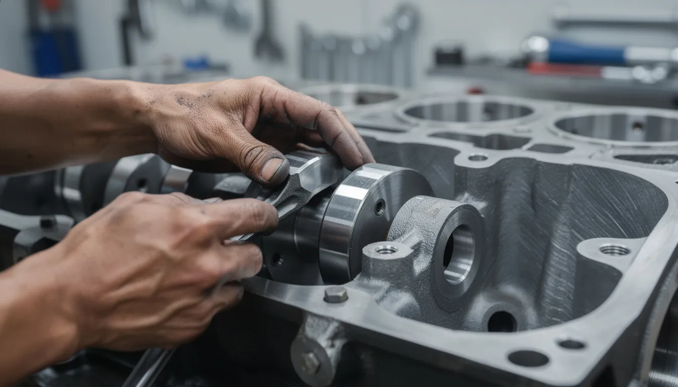
Installing New Crankshaft Main Bearings
Install upper main bearing shells into the block saddles. Verify that locating tangs align with notches and oil holes line up with block passages.
Installation sequence:
- Apply clean engine assembly lube or fresh engine oil to bearing surfaces
- Carefully lower the crankshaft into position with assistance—don't nick the journals
- Install lower bearing shells into caps, aligning tangs
- Apply lube to lower bearing surfaces
- Install caps in their original positions and orientation
Torque main caps following the manufacturer's pattern—typically from the center outward—in several stages. Use a calibrated torque wrench. If the specification calls for angle tightening, use an angle gauge.
After torquing, verify crankshaft end play (thrust clearance) using a dial indicator. Compare the reading to service manual limits. Excessive end play requires thrust bearing replacement; insufficient clearance may indicate improper bearing selection or cap positioning.
Installing New Connecting Rod Bearings
Fit new upper bearing shells into the rod big ends and lower shells into the caps. Verify tang alignment and check for any debris between shell and bore—even a small particle causes problems.
Installation procedure:
- Apply assembly lube to rod bearing surfaces and crankpin journals
- Guide each rod onto its crankpin carefully—protect the journal from rod bolt threads
- Install caps in correct orientation (match marks aligned)
- Torque rod bolts in stages to specification, using angle if required
After installing each pair (or all rods on one journal), rotate the crankshaft by hand. It should turn smoothly without binding. Any tight spots indicate a problem—stop and investigate before proceeding.
Final Clearance Checks and Engine Reassembly
Before buttoning up the engine, perform a final verification:
- Plastigage at least one main and one rod bearing to confirm clearances are within range
- Inspect for uniform contact patterns where visible
- Verify all oil holes and grooves align with block and rod oil passages
Reassemble remaining components:
- Oil pump and pickup (verify pickup clearance to pan)
- Oil pan with new gasket, torqued to spec
- Timing covers and front components
- All sensors and accessories
Prime the oil system before first start. Some engines allow spinning the oil pump; others require pre-lubing through gallery plugs. This prevents dry startup damage.
On first run, monitor oil pressure closely. It should build within seconds and hold steady. Listen for any unusual sounds. After a short run-in period (typically 15-30 minutes at varying RPM), perform an oil and filter change to remove any assembly debris. Check the drained oil and filter for metal particles—verify that no abnormal contamination is present.
This section addresses practical questions that come up frequently during bearing replacement projects on heavy equipment engines.
FAQ
Q1: Can I install new bearings on a worn crankshaft without grinding it?
A1: Light, uniform wear can sometimes be managed with standard bearings if oil clearances remain within the service manual's acceptable range. The key word is “if”—you need to measure and verify. Deep scoring, visible taper, or out-of-round conditions require crankshaft grinding and undersized bearings. Forcing standard bearings onto a badly worn crankshaft leads to predictable results: short bearing life, low oil pressure, and the risk of a spun bearing that destroys both the crankshaft and the connecting rod. Measure accurately, consult a machine shop if needed, and then contact Fab Heavy Parts for the correct bearing size based on final journal dimensions.
Q2: Do I need to replace all main and rod bearings if only one failed?
A2: When a single bearing fails, metal particles circulate through the entire lubrication system. These particles embed in other bearings, causing damage that may not be immediately visible but will shorten bearing life dramatically. Best practice is to inspect every main and rod bearing during teardown. In most rebuild situations, replacing the complete set restores balanced clearances across all journals and provides the most reliable result. Fab Heavy Parts supplies complete bearing sets, making full replacement straightforward and cost-effective.
Q3: How often should crankshaft and rod bearings be checked in heavy equipment?
A3: Bearings are typically inspected during major overhauls or when symptoms appear—low oil pressure, knocking sounds, or metal particles detected in oil analysis. Unlike filters, they don't follow a strict calendar-based replacement schedule. Machines working in severe conditions or accumulating high hours between services may need earlier inspection. Regular oil analysis provides early warning of bearing wear through elevated copper or lead content. Maintaining oil quality, proper filtration, and cooling system health extends bearing life significantly between inspections.
Q4: Can I mix bearing brands or materials in the same engine?
A4: Mixing different brands or material types on the same crankshaft creates inconsistency. Each manufacturer may have slightly different thickness tolerances, crush characteristics, and wear behavior. What works fine individually may create uneven clearances when combined. Using a matched set from one trusted source simplifies installation and future service. If an engine already contains mixed bearings from previous repairs, the best approach during your next overhaul is replacing everything with one complete matched set from Fab Heavy Parts.
Q5: What should I do if my plastigage readings do not match the manual's clearance range?
A5: First, confirm that your procedure was correct: proper torque values, calibrated tools, crankshaft not rotated while plastigage was in place. Small errors in technique cause misleading readings. If readings are still out of specification after re-checking, you have decisions to make. A different bearing thickness might restore proper clearance. The crankshaft may need grinding to the next undersize. Housing bores might require machining. Record your measurements and contact Fab Heavy Parts—we can help you select bearings or plan next steps based on your actual data.
Recommended Crankshaft Bearing/ Con Rod Bearing at Fab Heavy Parts
1.
 New Isuzu Engine 4JB1 Con Rod Bearing and Crankshaft Bearing Set
Condition: new, aftermarket
Engine Fitment: The Con Rod Bearing and Crankshaft Bearing Set fits for 4JB1 Isuzu
2.
 New Deutz Engine F2L511 Crankshaft and Con Rod Bearing 02234014 Replacement
Part Number: 02234014
Condition: new, aftermarket
Engine Model Number: The Crankshaft and Con Rod Bearing fits for F2L511
3.
 Kubota V1505 Engine Main Bearing and Con Rod Bearing Set, STD
The Main Bearing and Con Rod Bearing Set fits for Kubota tractor, loader, mower, excavator, etc.
4.
 6207-31-3300 Con Rod Bearing Fits for Komatsu 6D95-5 Engine PC200-5 PC220-5 Excavator
Part Number: 6207-31-3300
Application: The Con Rod Bearing fits for Komatsu PC220-5 PC200-5
5.
 New Fits Cummins Engine NT855 855 Connecting Rod Bearing 214950
Condition: new, aftermarket
6.
 New 6D22 Engine Con Rod Bearing Connecting Rod Bearing Aftermarket for Mitsubishi Fuso Truck
For engine 6D22
Condition: new, aftermarket
Application: The Con Rod Bearing Connecting Rod Bearing fits for Mitsubishi Fuso truck with engine 6D22
FAB Heavy Parts: Your Trusted Engine Parts Supplier
Welcome to Fab Heavy Parts' online catalog, your trusted source for quality auto parts and tools. Explore our extensive selection of Engine Bearings and more. Avoid delays by securing the parts you need from a reliable supplier who keeps inventory moving. Our expert team is here to provide personalized support, ensuring you get the right parts. Reach out today to stay ahead and keep your operations seamless!